 THE BHOGART PROJECT
merk updated this page on: March 22 2026 06:11:30.
MONDAY
remember to clean the inside of the system and RE-DO THE MICRON-FILTERS!
swap out fittings for butane tank- check inlet fitting on evaporation chamber too.
open recovery tank and verify the straw connection is going to the in-valve at the top of material chamber
PERFORM VACUUM TEST
PERFORM PRESSURE TEST
INTRODUCE SOLVENT INTO EVAPORATION CHAMBER
DISTILL SOLVENT
DISASSEMBLE AND CLEAN SYSTEM OF CONTAMINANTS
LOAD PLANT MATERIAL AND MOLECULAR SIEVE BEADS
REASSEMBLE, PERFORM VACUUM AND PRESSURE CHECKS
PURGE AIR FROM MATERIAL TUBE (IF ANY)
..
BEGIN EXTRACTION
RECOVER
SHUT DOWN
CLEAN
STILL NEED:
1) *refrigerant scale $60
2) *immersion heater $30
3) *small water pump $15
4) dessicant-drier filler | molecular sieve beads (TYPE 3A)
*explosion proof
STILL WANT:
1) vacuum oven
2) nitrogen, tank, hose, and fittings
3) honeypot stand
4) heat exchanger stand
5) system wall-anchor
6) a KEGERATOR (or similar) to keep tank cooled without icebath
7) Acetone (for internal cleaning)

Loading New Solvent
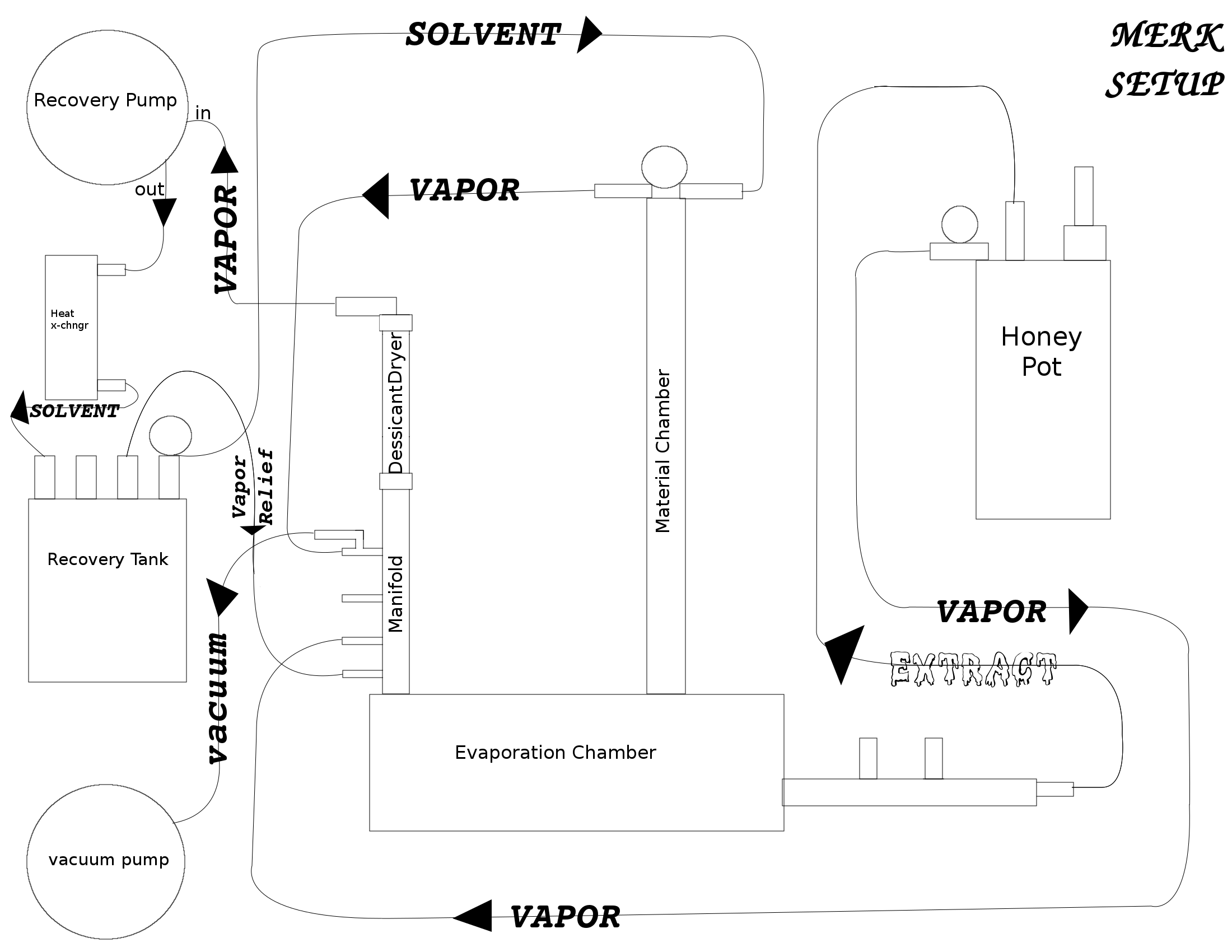
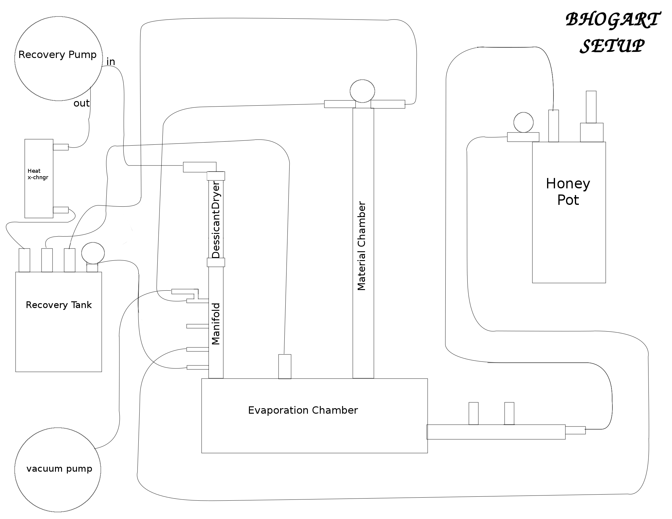
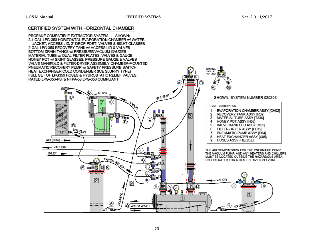
Reference the system diagrams in the Appendix. Use proper eye, hand and clothing PPE to protect from frostbite and fire. Ensure proper ventilation is operating effectively and warning sensors are working. If purified LPG solvent is supplied, recovery tanks can be filled directly through the valve #E tank inlet, but distilling to purify even high-grade solvent is recommended. Take care to prevent tank overfilling. Never load liquid solvent in excess of 80% of the recovery tank volume, as space for thermal expansion must be maintained to prevent the safety valve from blowing-open and releasing LPG into the area. Follow all standard LPG tank-to-tank fill procedures. New LPG solvent should be purified by distillation using the system’s filter-dryer system. The new solvent is loaded into the evaporation chamber, as follows:
1) After the system has passed initial vacuum and pressure checks and the filter-dryer assembly is loaded for solvent cleaning, again pull a vacuum on the system and verify closed-loop tightness. It is CRITICAL THAT ALL AIR IS PURGED FROM THE SYSTEM BEFORE LOADING ANY LPG.
2) Close all valves to isolate the various assemblies while maintaining this complete vacuum.
3) Attach the solvent-filling hose from a solvent supply tank dip tube outlet to valve #N direct-inject. Leave valve #N closed for now.
4) Open the dip tube valve on the solvent supply tank to pressurize the hose.
5)"Burp-Purge" the hose to remove any air: Use a wrench to protect hands, slowly unscrew the hose fitting at valve #N until a little solvent just bar ely starts to squirt out – purging the air out of t he hose – and quickly screw back the fitting and tool-tight en. Minimize the release of LPG into the air.
6) To track solvent use by weight, a scale is neede d under the solvent supply tank Before transferring the solvent, record the starting weight (or"zero" the tare) on the scale. Note: Make sure the scale i s safe for use in an explosive atmosphere.
7) Leaving all other valves closed, open valve #N – solvent will shoot into the evaporation chamber.
8) The gauge on the chamber will show rising pressu re. The pressures in the two tanks may equalize, in which case the flow will slow then stop. If the pressure equalizes, warming the source tank with warm water will raise the vapor pressure and transf er more solvent.
9) As solvent flows into the evaporation chamber, w atch the scale to prevent overfilling. Never load liquid solvent in excess of 80% of the recovery tan k volume. Depending on the size of the evaporation chamber, it may take multiple cleaning loads to fill a large recovery tank.
10) Close valve #N on the evaporation chamber and t he close the valve on the solvent supply tank. The supply tank should then be removed from the area. A small amount of LPG will be lost to the air when the hose is disconnected (the shorter the hose the better); proper ventilation is mandatory.
Purifying New Solvent
Reference the system diagrams in the Appendix. T he new solvent will distilled by vaporization in th e evaporation chamber, pumped through the filter- dryer for cleaning, and condensed into the recovery tank, which is under vacuum or partly filled.
1) After Loading New Solvent , all valves of the system are closed. Open all val ves #B, #C, #D and #E and turn ON the recovery pump – solvent vapor will begin flowing from the chamber, through the manifold, filter-dryer, recovery pump and heat exch anger, into the recovery tank.
2) Run the evaporation chamber warming system at ab out 60°F to vaporize the solvent without boiling contaminants. Warming the chamber is vital to provi de the energy to evaporate the liquid LPG.
3) The heat exchanger condenser needs to operate wi th ice water or coolant below 40°F to remove that added heat energy and help condense the LPG ba ck into liquid.
4) The recovery tank now contains both vapor and li quid LPG. While the recovery pump is running, remove vapor to reduce recovery tank backpressure b y opening valve #K, the"first valve" on the manifold, and open one-fourth-turn (1/4 th ) the #Ki vapor relief ( VR 2 ) needle valve on the recovery tank. As the pump runs and solvent is transferred, the pressure in the evaporation chamber will slowly go down. To get below about 10 psi, close th e #K and #Ki valves to stop the vapor recycling.
5) Before all solvent is vaporized and some liquid remains in the evaporation chamber, close valve #B so chamber pressure can rise, then drain the last o f the solvent into an empty HoneyPot TM to flush the contaminants out of the evaporation chamber. Se parately vent and clean the HoneyPot TM .
6) After draining, open valve #B and complete all e vaporation from the chamber down to a vacuum.
7) Close valves #B, C, D, and E, and then turn OFF the recovery pump. The new solvent is now purified and in the recovery tank. Turn OFF any heating and cooling devices in use.
8) Inspect the evaporation chamber, which should be clean and ready for use, but if contamination is visible the chamber will need cleaning. Solvent can be added through valve #N for additional flushing, or the evaporation chamber can be opened for manual cleaning.
9) To open the evaporation chamber, properly vent t he chamber as some LPG vapor will remain. Open an access port of the evaporation chamber. Wit h vertical chambers, lift off the material tube assembly, valve and adapter. Remove the gasket for possible reuse.
10) Clean the inside bottom of the chamber as neces sary to remove any residue. Use isopropyl alcohol or acetone and towels to wipe the bottom clean. A s olvent-safe hand spray bottle with 75% IPA and 25% acetone is helpful. Avoid sloshing cleaning sol vent as it may dirty more of the inside surface. Use appropriate gloves, eye protection, respirator and ventilation for the cleaning solvent in use.
11) Reinstall the access port cap or adapter and va lve. Note: Due to contaminants in the new solvent, it may be preferable to reload the filter-dryer now. Loading the Material Tube Reference the system diagrams in the Appendix.
T he material tube assembly will be loaded with the h erbal material and the filtering media. Note: Systems with multiple material tubes simultaneousl y connected may be extracting from one material tube while another tube is being reloaded. See the separate section below for details.
Disassemble, empty and clean the Material Tube Asse mbly
Warning: Before starting, ensure no pressurized gas is in t he material tube assembly to be loaded. Verify that all shutoff valves at the top and botto m of the material tube are closed.
1) Open the top TC clamp and set aside the material tube lid with valves and hoses attached.
2) Open the bottom TC clamp at the top of the conce ntric reducer, remove the material tube stack and transfer to the Material Tube Reloading Station. Re tain gaskets for possible reuse. W ith rack-mounted material tubes, the TC heads w/ va lve used instead of concentric reducers may stay with the system or by disconnecting extract hoses g o with the rack to the reloading station. Note: A Material Tube Reloading Station needs ample vent ilation to vent the LPG retained in the spent plant material. Thorough vapor recovery from the ma terial tubes can greatly reduce this factor.
3) Open the TC clamps at the top and bottom of the material tube spool, remove both filter plates, remove the spent herbal material from the tube spoo l for proper disposal, and dispose of any spent filter media from both filter plates. Retain gaske ts for possible reuse.
4) Clean the material tube spool and filter plates as needed.
Load and Reassemble the Material Tube Assembly
1) Take a micron filter screen and insert it into a filter plate together with the c-ring, so the scre en is flat and covers all sides of the c-ring, making sur e the screen fits evenly. Stack as many filter screens and c-rings as desired and hold with the c- ring-clip.
2) Place a TC screen gasket on the ferrule on that end of the filter plate.
3) Place the material tube spool onto that screen g asket and secure to the filter plate with a TC clam p.
4) Pack the herbal plant material that has been dri ed and trimmed as preferred into the tube evenly and tightly working completely to the top, avoiding air gaps or dense spots. Note: The means of drying and degree of dryness of the h erbal material will vary depending on individual preferences. Avoid damp material that wi ll introduce excessive water. Specific recommendations for trimming or grinding the materi al, the size of pieces and degree of packing are outside the scope of these instructions. Avoid mach ine grinding powder that may prevent solvent flow.
5) Load the top filter plate with a filter screen l ike in step 1.
6) Place a TC screen gasket on the ferrule at the t op of the loaded material tube spool.
7) Place the top filter plate onto that gasket and secure with a TC clamp. R eturn the loaded material tube from the reloading s tation to the system location...
8) Place a TC gasket on the open concentric reducer on the chamber and carefully lift the loaded material tube stack and place onto that gasket, sec ure with a TC clamp. With rack-mounted material tubes, reinstall the TC heads w/ valve or connect the extract hoses.
9) Reinstall the material tube lid using a TC gaske t, secure with a TC clamp.
10) Verify that all the clamped connections just re assembled are properly seated and secure. Note: Multiple material tube assemblies can be preloaded for quick exchanges later.
Purging Air from the Material Tube
Reference the system diagrams in the Appendix. Note: Systems with multiple material tubes simultaneousl y connected may be extracting from one material tube while another tube is being reloaded. See the separate section below for details. T his assumes a freshly loaded material tube is insta lled. All air must be purged from the system:
1) Open valve #Gi material tube vapor outlet, with all other valves closed (#G remains closed).
2) Turn on the vacuum pump or with the vacuum sourc e available: open valve #F to apply vacuum to just the material tube.
3) Watch the material tube pressure gauge – it shou ld drop to a near total vacuum, reading about 29-InHg. The exact value will vary with the altitud e (less at higher altitudes).
4) If hose #A has air in it, open valve #Ai materia l tube inlet (#A remains closed).
5) If the evaporation chamber is not isolated under vacuum (and not being kept sealed with extract during a material tube reload) open valves #B and # G to apply vacuum to the evaporation chamber.
6) The recovery pump and heat exchanger assemblies should still be isolated under vacuum; if not, also open valves #C and D, with #G open (#E remains closed).
7) The HoneyPot™ assembly should still be isolated under vacuum; if not, also open valves #J, Ji and Hi, with #G open (#H remains closed), or use the se parate vacuum port if the HoneyPot™ has one.
8) Once the gauge is stable at about 29-InHg, close valve #F. The vacuum pump may be turned off.
9) Note the time. The vacuum should hold for at lea st ten minutes. If the vacuum is not held, the vacuum check has failed; find and correct the leak before running the system any further.
10) Close all valves; the system is loaded and unde r vacuum.
Extracting from the Material
Reference the system diagrams in the Appendix. Note: Systems with multiple material tubes simultaneousl y connected may be extracting from one material tube while another tube is being reloaded. See the separate section below for details. Note: The extractor system runs by differential pressure between the recovery tank and the material tube/evaporation chamber. There needs to be a start ing pressure of at least 20 psi in the recovery tan k (check the gauge) for the system to run properly. P ure propane achieves this pressure at about 0°F , but pure butane needs to be almost 80°F to provide this vapor pressure (LPG mixtures are be tween these temps). The vacuum in the material tube will pull s ome cold low-pressure solvent from a tank, but usually not enough. It may be possible to use the r ecovery pump to pressurize the recovery tank for system operation with cold solvent. T his assumes a freshly loaded material tube is insta lled, solvent is ready in the recovery tank, all ai r has been purged from the system, and all valves are clo sed; use proper PPE as previously discussed:
1) Open valve #Ai material tube inlet. Then open va lve #A recovery tank outlet. Solvent will shoot up hose #A into the material tube (the hose may wiggle with the liquid flow). Solvent expansion into the vacuum will cause immediate chilling at the top of the material tube as the tube fills with solvent.
2) When the material soaking dwell time has elapsed , or immediately if not soaking, open big valve #M on the evaporation chamber under the material tube. Extract solvent will flow through the herbal material and filter media into the evaporation cham ber.
3) Close both valves on hose #A before the evaporat ion chamber can be overfilled, or when the pressure on the evaporation chamber gauge equals th e pressure on the recovery tank gauge as the extraction flow has stopped.
4) In time, it may be preferable to close big valve #M to stop draining the last of the solvent extrac t that may contain mostly undesirable solutes. Viewing the flow through a sight glass may help with this. Note: Not running the recovery pump during extraction le ssens freezing due to LPG expansion and reduces vaporization in the material tube. Wait unt il solvent is about one inch deep in the evaporatio n chamber before starting the recovery pump.
Multiple Material Tube Use Systems with multiple material tubes simultaneously connected are intended for sequential extraction. Extraction from one material tube needs to be compl eted before starting extraction from the next material tube. However, vapor recovery from an extr acted material tube can continue while the next material tube undergoes solvent extraction. Evaporation chambers with multiple drop tubes for m ultiple material tubes are intended to minimize system downtime loading tubes by allowing extractio n from one material tube while reloading another. Rack-mounted material tubes take this approach furt her, allowing setting-up a system for continuous extraction without single material tube exchanges. Whole racks of material tubes can be exchanged. Whether chamber-mounted or rack-mounted, close atte ntion must be directed to proper valve use to operate multiple material tubes safely and effectiv ely. Control between material tubes is primarily by the valves at the material tube lids (#Ai and #Gi), as valves #A and #G will mostly remain open. Rack- mounted setups also require attention to the extrac t hoses and valves at the bottom of the tubes. Attention is also needed to ensure the evaporation chamber is not overfilled during continuous extraction. The rates of extraction and solvent rec overy will vary widely with the solvent mix, temperatures and pressures in use, equipment types and sizes comprising the system, recovery pump and heat exchanger effectiveness, and numerous oper ating techniques.
Recovering the Solvent Reference the system diagrams in the Appendix.
S olvent will be separated from the extract in the ev aporation chamber and returned to the recovery tank . Note: It may be desirable to start the solvent recovery process before the extraction is finished. A ny evaporation chamber warming system should be ope rating to help evaporate the solvent. This heating should be set for 70°F to 80°F (21°C to 27° C). T he heat exchanger should be pre-chilled by coolant, ice water or ice slurry, depending on the set-up, at 40°F or less. Follow the instructions for the model heat exchanger and coolant system in use. T his assumes extract solvent is in the evaporation c hamber, the filter-dryer is ready to process solven t, and the whole system remains gas-tight:
1) Open all valves #B, C and D to the manifold, pum p and heat exchanger.
2) Turn ON the recovery pump and open valve #E reco very tank inlet. Solvent will evaporate in the chamber leaving the extract behind, be purified thr ough the filter-dryer, condensed in the heat exchanger, and stored back in the recovery tank.
3) Watch the pressure gauges: the higher the pressu re in the evaporation chamber the more efficient the recovery pump will run.
4) The recovery tank contains both vapor and liquid LPG. The pressure in the recovery tank should be 20 psi to 50 psi depending on the solvent mix (lowe r with butane, higher with propane). While the recovery pump is running, the tank pressure rises, which can slow recovery. Remove some of the tank vapor pressure by opening valve #K, the"first valve" on the manifold, and open one-fourth-turn (1/4 th ) the #Ki vapor relief ( VR 2 ) needle valve on the recovery tank. Adjust the #Ki valve to control the recovery tank pressure. The more the #Ki valve is open the lower the recovery tank pressure, but if too low then excessive vapor is recirculatin g, which will slow the pumping and recovery will actually take longer.
5) Close big valve #M to stop draining the last of the solvent extract that may contain mostly undesirable solutes. Viewing the material tube flow through a sight glass may help with this.
6) Open both valves on hose #G to recover solvent r emaining in the material tube. If so equipped, warming the material tube will help vaporize the so lvent remaining in the herbal material.
7) When the evaporation chamber pressure drops to a bout 10 psi, or the extract is as thick as desired, close valves #B and #M to stop further evaporation. Material tube vapor recovery may continue; if the material tube recovery finishes first, close bo th valves on hose #G and the material tube can be exchanged or reloaded while solvent recovery contin ues.
Transferring the Extract
Reference the system diagrams in the Appendix. E xtract will be transferred from the evaporation cha mber to the HoneyPot™ for further processing and to free the extractor for additional material extracti on. T he recovery pump is still running, valves #B and #M are closed, both valves on hose #G may be open, valves #K and Ki are open, and the HoneyPot™ includ ing hoses #H and #J are under vacuum:
1) Open both valves on hose #H evaporation chamber drain; the extract solution will transfer into the HoneyPot™. Be careful not to overfill the HoneyPot™ . Multiple HoneyPots™ may be needed to hold a full extraction run, especially if multiple material tubes are extracted.
2) Open both valves on hose #J, if necessary to suc k extract solution from the chamber.
3) Close valve #H evaporation chamber drain to stop HoneyPot™ filling.
4) Continue to remove solvent vapor from the HoneyP ot™ through the #J hose to achieve the desired thickness of the extract, depending on one’s prefer ence for further extract processing.
5) Close all valves on hoses #H and #J to complete the transfer. Note: The HoneyPot™ can be exchanged for an empty unit a nd the transfer process repeated. Be sure to remove air from hoses #H and #J as well as the H oneyPot™ – use a"T-Valve" hose tap fitting on the #J hose if the HoneyPot™ lid is not equipped with a vacuum port.
Note: Recommendations for further processing the extract are outside the scope of these instructions.
System Shutdown
Reference the system diagrams in the Appendix. Warning: Always be certain all pressure is relieved from a v essel or accessory before opening any clamp, closure or hose. Pressurized closures can ex plode open, causing damage or injury, and sudden decompression of LPG can cause frostbite to any exp osed eyes or flesh. Check all pressure gauges. T he recovery pump is still running and valves #B and M are closed:
1) Complete all solvent recovery from the evaporati on chamber and material tubes: open valves #B, G and Gi as necessary and wait for the chamber pressu re to be a vacuum (0 to 22-InHg).
2) Close valves #C, D, E, G, Gi, K and Ki, and then turn OFF the recovery pump. The solvent is now purified and in the recovery tank and the extract h as been transferred to one or more HoneyPots™.
3) Turn OFF any heat exchanger pump and evaporation chamber heating system in use.
4) Open briefly then close the valves on hose #E to drain any liquid LPG condensed in the heat exchanger into the recovery tank.
5) Ensure all valves are closed.
6) To keep the evaporation chamber and filter-dryer sealed while reloading a materiel tube, keep valves #B and M closed until starting the next"Extracting from the Material" step. Continue at the"Loading the Material Tube" section.
7) Only if opening the system to air: The evaporati on chamber and material tube(s) should be under a slight vacuum, release this vacuum by opening valve #L manifold inlet to allow air in while opening valves #B, G and Gi. If slightly pressurized, use t he vacuum system through valve #F to safely remove the remaining vapor, then open to air. This may allow a small release of LPG vapor.
8) If not keeping the chamber sealed, an evaporatio n chamber access port may be opened to manually collect any remaining extract residue or t o clean the inside of the chamber. This may be unnecessary if immediately running another extracti on batch or using solvent cleaning techniques.
9) Contingent on how many contaminants were in the solvent vapor, primarily water from the herbal material, it may be necessary to replace the filter disc and desiccant pellets in the filter-dryer. Desiccant replacement after every full run is recom mended as inexpensive quality insurance. The filter-dryer can be isolated from the evaporation c hamber by keeping valve #B closed, and evacuated of air by the vacuum through valve #F.